


FEP/PFA Encapsulated O-Rings
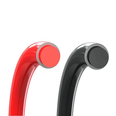
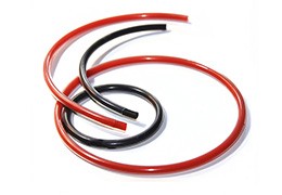
Encapsulated O-rings combine an elastomeric core (Silicone/FKM) with a seamless FEP/PFA jacket. This hybrid construction merges universal chemical resistance with high-resilience sealing, significantly outlasting standard rubber seals in extreme thermal and corrosive environments.
Material Selection Matrix: FEP vs. PFA
The outer jacket is the primary barrier. We offer two distinct fluoropolymers based on thermal and mechanical requirements.
| Performance Metric | FEP (Fluorinated Ethylene Propylene) | PFA (Perfluoroalkoxy) |
| Continuous Service Temp | -60°C to +205°C | -60°C to +260°C |
| Mechanical Strength | Standard | Excellent (High Creep Resistance) |
| Permeability | Low | Ultra-Low (Semiconductor Grade) |
| Chemical Resistance | Universal (pH 0-14) | Universal (pH 0-14) |
| Typical Applications | Pumps, General Chemical, Food/Bev | Semiconductor, Aerospace, High-Temp Valves |
Core Selection Logic:
Solid FKM Core (90-95 Shore A): Optimized for high-pressure systems where superior compression set resistance is mandatory.
Solid Silicone Core (85-90 Shore A): General-purpose industrial standard with excellent thermal stability.
Hollow Silicone Core (75-80 Shore A): Designed for low-torque, low-pressure applications requiring high flexibility.
Technical Specifications & Tolerances
We manufacture to AS568, JIS B2401 (P/G/S/V), and Metric standards.
| Cross-Section (C/S) Range | Dimensional Tolerance (±) | Typical Application |
| 1.00 – 1.79 mm | 0.07 mm | Micro-valves / Precision Instruments |
| 2.65 – 3.54 mm | 0.09 mm | Standard Hydraulic/Pneumatic Systems |
| 5.30 – 6.99 mm | 0.13 mm | Large Bore Flanges / Pressure Vessels |
| 10.01 – 15.00 mm | 0.25 mm | Heavy-Duty Chemical Reactors |
Engineering Best Practices: Groove Design
Groove geometry is critical to prevent jacket cracking. Dimensions vary depending on the media (Liquid vs. Gas).
Groove Design Guidelines (Sample Values):
| C/S (mm) | Groove Depth (Liquid) | Groove Width (Liquid) | Groove Depth (Gas) | Groove Width (Gas) |
| 2.62 | 2.30 mm | 3.10 mm | 2.35 mm | 3.10 mm |
| 3.53 | 3.10 mm | 4.20 mm | 3.25 mm | 4.20 mm |
| 5.33 | 4.70 mm | 6.40 mm | 4.95 mm | 6.40 mm |
| 6.99 | 6.30 mm | 8.40 mm | 6.60 mm | 8.40 mm |
Lead-in Chamfers: Essential for assembly. Recommended angle: 15° to 20°
Pre-heating: For tight installations, immerse the seal in hot water (60℃-80℃) for 5 minutes to increase jacket flexibility.
Pressure Performance Matrix
Maximum allowable pressure is a function of hardness, cross-section, and the radial clearance gap.
| Hardness (Shore A) | 35 KG/CM² (3.5MPa) | 105 KG/CM² (10.5MPa) | 210 KG/CM² (21MPa) | 350 KG/CM² (35MPa) |
| 70 Shore A | Max Gap 0.15mm | Max Gap 0.05mm | - | - |
| 80 Shore A | Max Gap 0.20mm | Max Gap 0.10mm | Max Gap 0.03mm | - |
| 90 Shore A | Max Gap 0.25mm | Max Gap 0.13mm | Max Gap 0.08mm | Max Gap 0.03mm |
Failure Prevention Analysis
Rapid Gas Decompression (RGD): Not recommended for high-pressure gas cycles with sudden pressure drops; high risk of jacket rupture.
Chemical Swelling: Ensure core compatibility. If a medium permeates the jacket and the core swells, internal tension will cause delamination.
Mechanical Erosion: Manage clearance gaps according to the hardness table to prevent extrusion into the gap.
-
 Encapsulated O ringsThe encapsulated O rings are made of silicone rubber or fluororubber core and wrapped in an FEP or PFA outer shell....Read more
 -
 TES Teflon® Encapsulated Seals – OEM Replacement Plates & Rings for Nordson-Compatible MeltersDiscover OEM-equivalent TES Teflon® Seals for Nordson melters. and custom-fit for BM200, VD200, DD200, 5506, 5550,...Read more
